How to Make an Assembly in Fusion 360
Presented by

It's time to talk about everyone's favorite topic. Mating. (You two in the back stop snickering.) We're in part three of our under-the-covers *snicker* peek at Fusion 360 and this time, we look at Assemblies. Over the years we've passed along tips and tricks, best practices, and overall bad-assery when it comes to parametric modeling and assemblies. It burns the nostrils to say this a bit, but I want you to forget about mates for a few minutes. Or rather, let's think about how we would build assemblies without mates. Ready?
"Where we're going, we don't need mates."
– A nerdy cad nerd somewhere
If you're a SolidWorks or Solid Edge user, you're comfortable with building assemblies by mating components together. But even before that, you consider how to build and organize the parts and assemblies? Bottom-up? Top-down? Sketch-driven? Parametric modeling is great for many, but not so friendly for conceptual modeling. I faced this frustration many times when just wanting to model up an idea–thinking about assembly structure when I just wanted to think about assembly design. Sound familiar at all? Well, this is where Fusion 360 approaches assemblies a little differently.
In our first article, I mentioned five features in Fusion 360 and one of those features was As-Built Joints. I'll cover that feature here in a moment, but it will make more sense if we have a better understanding of top-down design (or layout, skeleton, or multi-body modeling). A smarty-pants, scholarly person on Wikipedia described top-down design as "breaking down of a system to gain insight into its compositional sub-systems in a reverse engineering fashion." What-evs. Here's my definition of top-down design: Creating parts in context of an assembly. You know, in contrast to bottom-up modeling: Creating parts and adding them to an assembly. Now, let's break these down and see how Fusion 360 approaches it differently.
Top-Down Design
I'm going to pretend for a moment I haven't spent 20+ years making sure my assemblies properly reference my parts. Yet, just this week I opened a model and somehow all references were lost. It wouldn't have been so bad, except that there were over 100 unique parts in the model.

There are other things we just accept as normal. Things we write manuals and methodologies around. Things like: renaming a file while keeping the reference, breaking up an in-context assembly parts to reassemble them, editing each part separately to apply a simple fillet to both of them, or going even deeper and editing sketches that drive multiple features to fix something that went wonky. Normal, everyday assembling modeling life, right?
Well, if you were to wad those processes up, fire them into the sun and re-write a CAD system, how would you do it differently? Let's start with sketches. My favorite top-down approach is to use sketches to drive multiple parts. In Fusion 360, a sketch is available to any feature, body, or component in a design without the need to copy or convert it. There's no need to edit each part separately to change your sketch or add features. Features can be applied across multiple bodies or components, all during the same active command. Joining a feature to an existing body and adding a new body (or component) is all done within the same command. Here's just a small example:

What I'm getting here is that, this multi-body approach within Fusion 360 doesn't interfere with your ability to model assemblies quickly. Instead of moving in and out of parts, you work on the design as a whole. You create bodies, turn them into components, and edit everything as if it were one. The shock and joy to me in all of this? You start thinking, primarily, how features affect the entire design, not just the individual part.
Mates vs. Joints
Ok, but what about Mates? After all, that's what we started off talking about. How does Fusion 360 handle bringing individual parts into an assembly? Instead of mates, you roll joints. (I promise that won't be the last 'joint' joke.) Are Joints just another name for Mates? Well, yes and no. Let's take a look at the difference.
In every CAD application I've ever used, Mates remove degrees of freedom and, in most cases, require multiple mates applied to each part to properly position and restrict movement. On the other hand, Joints define movement between two components. Now, since Fusion 360 starts by assuming zero degrees of freedom, in most cases, only one Joint is required to define the relationship (or motion) between components. I struggled with this at first, but, wow, have Joints made assembly time more laid back.
So, when you apply a Joints in Fusion 360, watch for the graphical feedback. After you select each part, the Joint will animate. The context menu that appears under the cursor is handy to quickly select a different Joint Type once you use it a couple of times, and spend a little time getting to know which Joint to apply to which situation.

Something that bugged me was setting up the equivalent of a Width (or Symmetry) Mate. It's there, you just have to right-click during the placement of a Joint and select "Between Two Faces". And, as in the example below, the 'Between Two Faces" option understands the context, applying the equivalent of a Width and Concentric in one operation. Disco.

As-Built Joints
Let's recap quickly. If top-down modeling is the prefered methodology for assembly modeling in Fusion 360, and Joints add a degree of freedom as opposed to multiple mates removing degrees of freedom, what would be the benefit of As-Built Joints? Well, I'm glad to pretend you asked, so I can ask you a question.
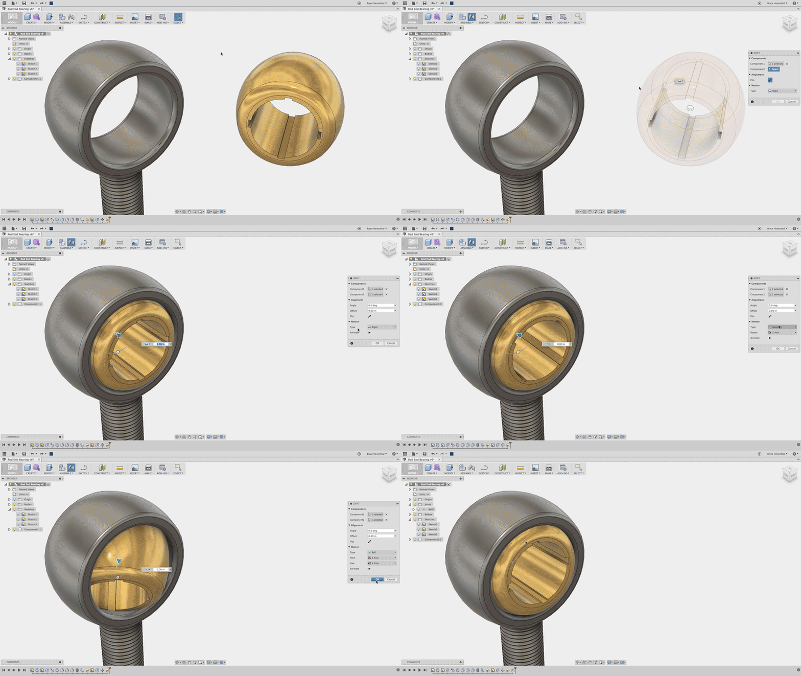
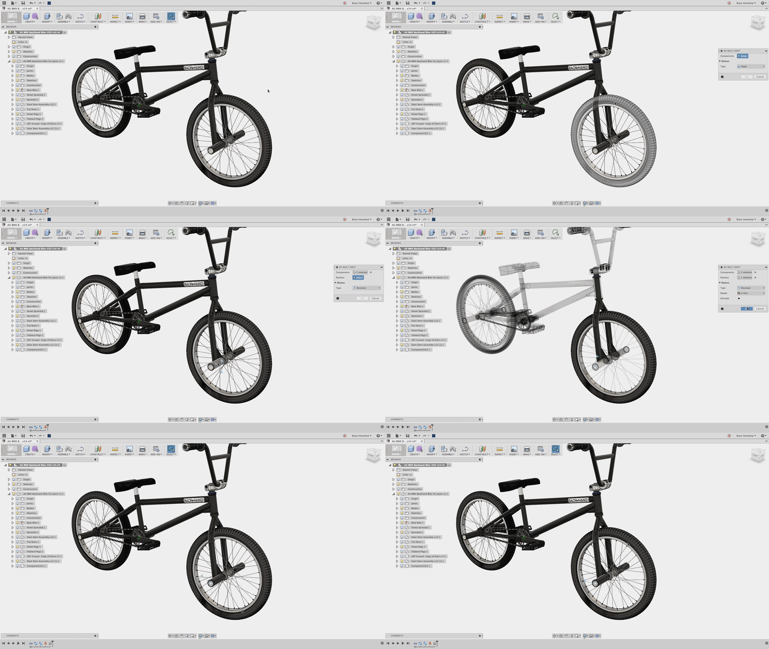
If you want to show mechanical motion, what sense does it make to model parts exactly where they go in the final assembly, if you have to disassemble them, only to assemble them again? Yet, that's how you do it to maintain the references. Most CAD software doesn't leave you with any other option but to do this. In Fusion 360 however, As-Built Joints assume the component is already defined by the sketch, so all that's left to do is to select the two components and determine the working behavior between the two by defining the type of motion.

Hopefully you see why I saved the best assembly feature for second to last. Joints and As-built Joints in particular save loads of time. It goes to the foundation of simplifying the product development process, starting with a top-down approach and working more efficiently with components. But we're missing one crucial aspect of completing our assembly. Bottom-up design.
Bottom-Up Design
So what you're saying here is that you have to model every part, every time as part of a top down design? No sir. And if you're seeing a theme in these posts, the folks over at Autodesk re-thought this little nugget, too. Not only can you create a reference to another component that will update when design changes are made, but let's imagine this situation: My colleague, let's call him Mr. Pita, is working on a part that is referenced in my assembly. He makes some horrible change that lights up my assembly tree brighter than the Griswold's cat at Christmas. Instead of having to resolve these issues, I can choose a version of Mr. Pita's file that was working previously.

Not sure exactly when they added this, it hasn't always been in Fusion 360, but sometime last year (June going by this feature overview) they added the ability to work collaboratively through Distributed Design with the option to Choose Version for a part that is already being used in your assembly.
On top of this, since the Fusion 360 data lives in the cloud, independent of file locations, and a team would be working from the same data, renaming files doesn't cause issues in Fusion 360. The references will automatically be updated.
Summary
These are the assembly features in Fusion 360 that are making me think differently about the design process. There are still some things I'm working through, like updating Joints after a geometry change, but maybe you have some tips for that. And yeah, of course you're going to consider the structure of the assembly up front, but with Fusion 360's approach to top-down design, you're not constrained by working within one part or another. You can work in context of the assembly across parts, you define movement between parts, and you build assemblies with less worry about references and a faster ability to choose versions. I don't think the time that all of this saves can be emphasized enough. If there are other assembly features I may have missed that have saved you time, definitely point them out. And if you haven't yet, you can try Fusion 360 here.
How to Make an Assembly in Fusion 360
Source: https://www.solidsmack.com/cad/four-fusion-360-assembly-features-that-will-make-you-forget-about-mates/
0 Response to "How to Make an Assembly in Fusion 360"
Post a Comment